Difference between revisions of "The role of surface displacement in landscape evolution"
| Line 1: | Line 1: | ||
| − | |||
| − | |||
| − | |||
| − | |||
| − | |||
| − | |||
{| class="wikitable" | {| class="wikitable" | ||
| + | |- | ||
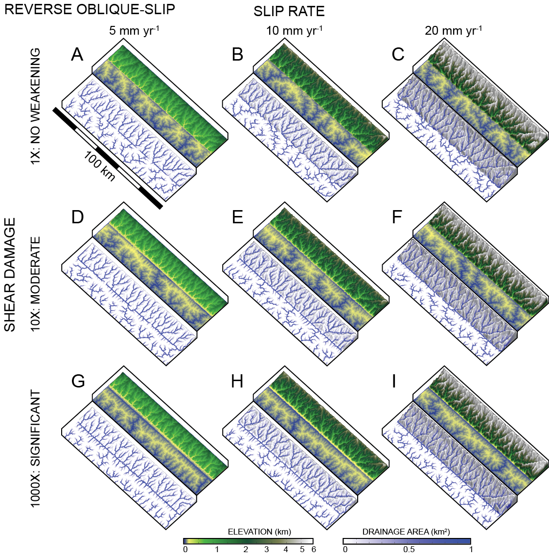
| + | ! style="width:500px" | The objective of this project is to study the effects of 3D fault slip on landscape evolution. Specifically, there can be implications for the steepness of rivers and the evolution of drainage network patterns when considering the full 3D solution for fault slip. | ||
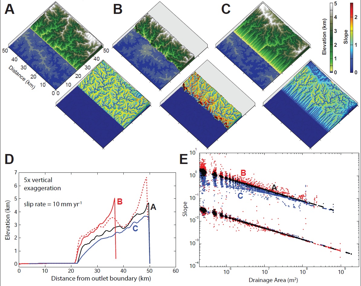
| + | ! style="width:500px" | [[File:kin_slope-v-area.jpg|500px|thumb|Experimental models used to determine influence of lateral surface motion on surface slopes. (A) Block uplift, no lateral motion (black); (B) reverse dip-slip (red); (C) normal dip-slip (blue). (D) E-W topographic profiles. (E) Slope versus area log-log plots]] | ||
|- | |- | ||
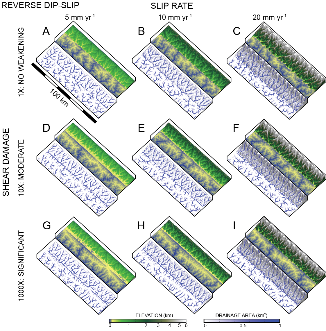
! style="width:500px" | [[File:kinematic-01.png|500px|thumb|left|Reverse dip-slip faulting]] | ! style="width:500px" | [[File:kinematic-01.png|500px|thumb|left|Reverse dip-slip faulting]] | ||
Revision as of 16:04, 6 May 2015
| The objective of this project is to study the effects of 3D fault slip on landscape evolution. Specifically, there can be implications for the steepness of rivers and the evolution of drainage network patterns when considering the full 3D solution for fault slip. | |
|---|---|
