The role of surface displacement in landscape evolution
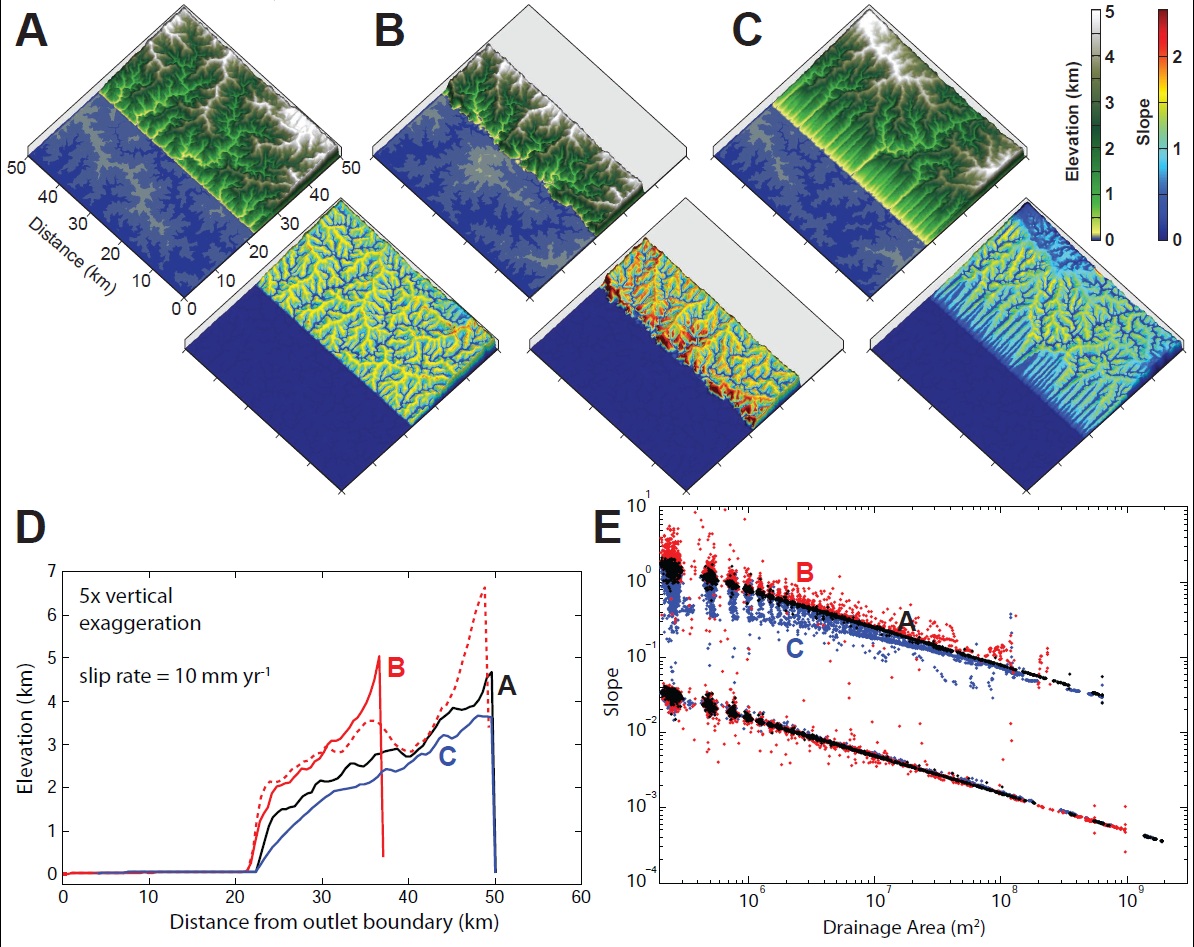
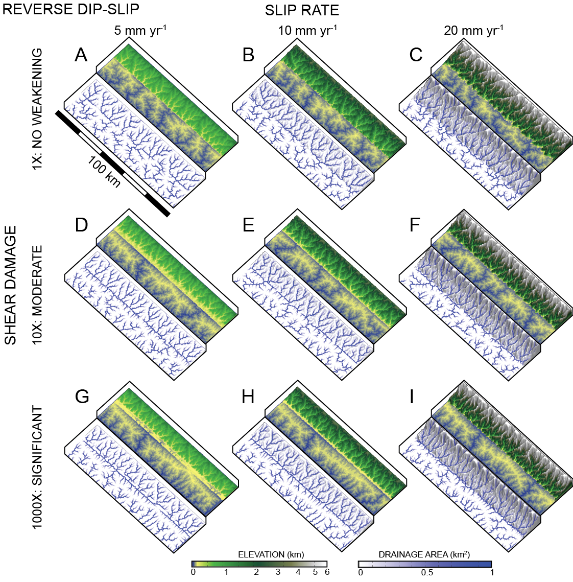
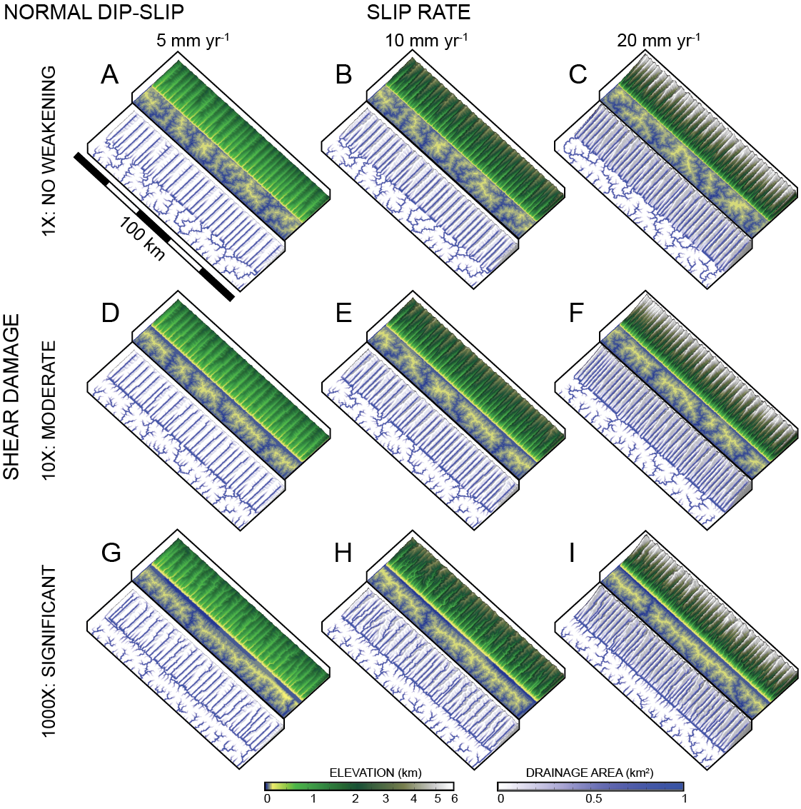
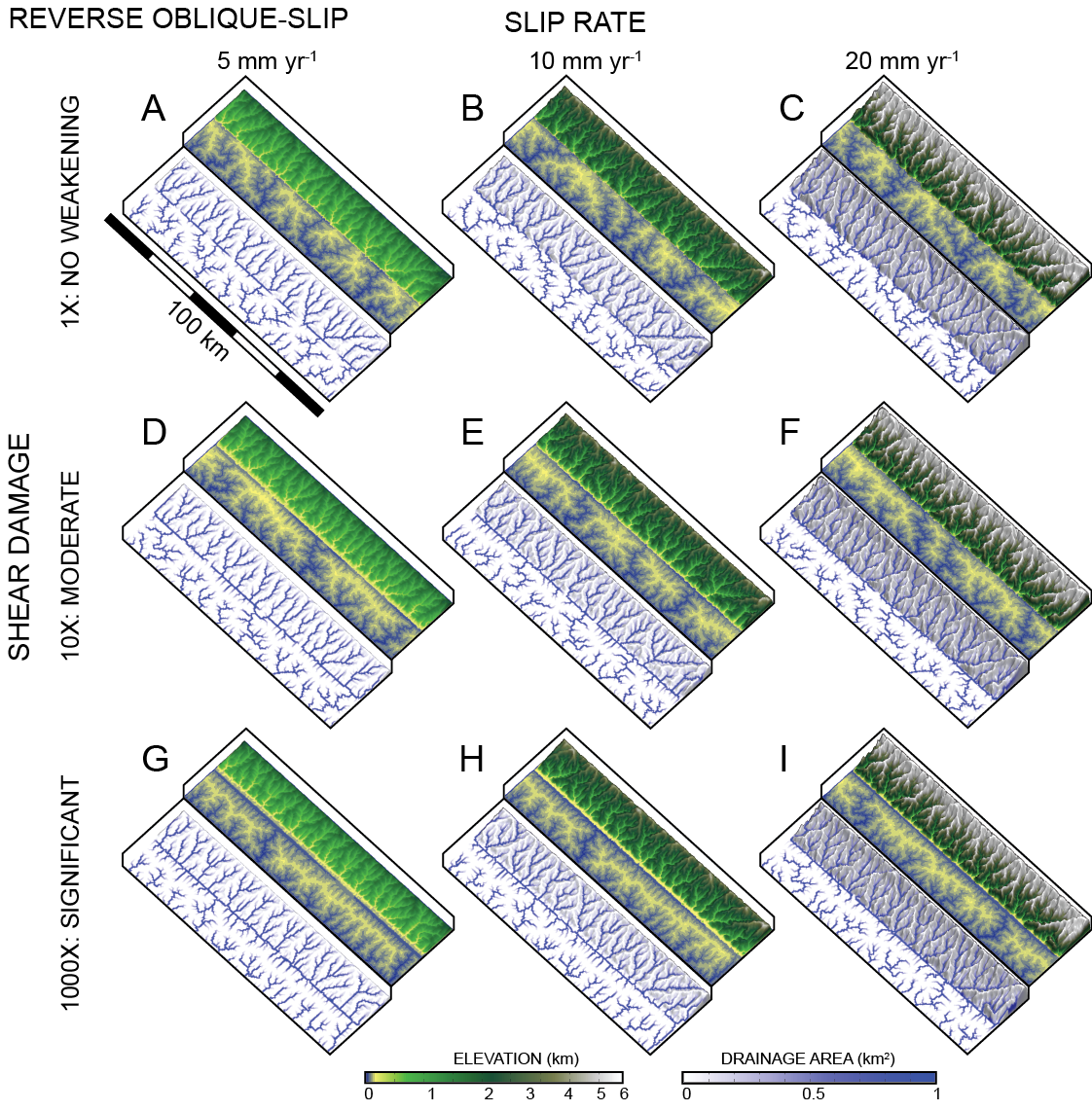
The objective of this project is to study the effects of 3D fault slip on landscape evolution. Specifically, there can be implications for the steepness of rivers and the evolution of drainage network patterns when considering the full 3D solution for fault slip. Our method is to apply kinematic conditions to points on a model landscape surface, representing tectonic motion, and allow for surface processes to erode the surface. Additionally we include rock damage associated with shear strain as an influence on rock erodibility surrounding the fault. Results suggest that the lateral motion attributed to slip along a fault plane can drastically increase channel slope in reverse thrust regimes and decrease slope in normal rift regimes, however, this depends on the dip angle of the primary slip surface.
Model results suggest three major ways in which rivers will align to fault structures:
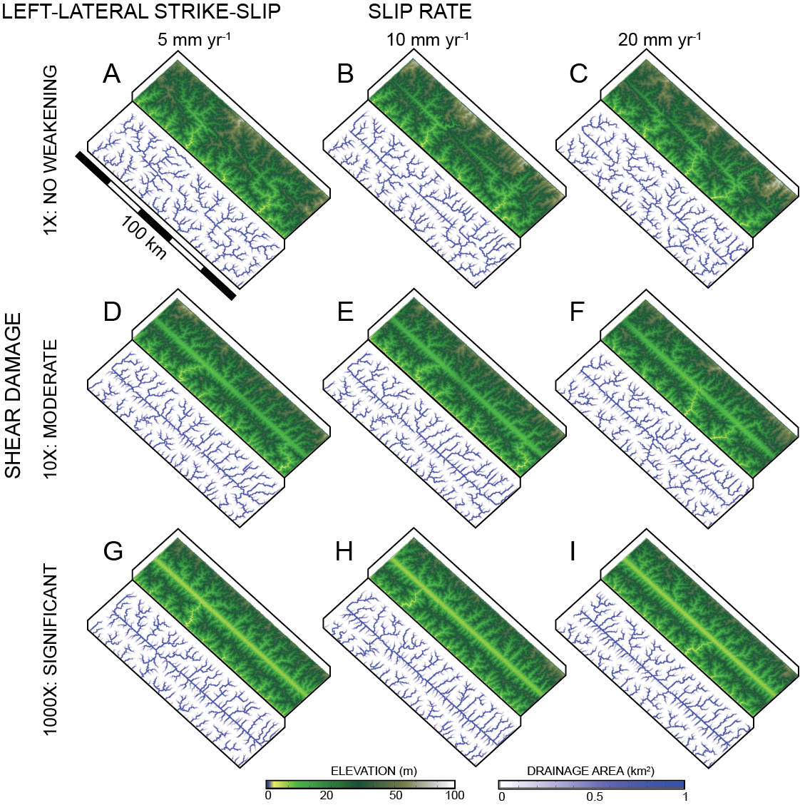
1. Kinematic: Strike-slip motion displaces rivers that cross the primary slip surface, extending their reach along strike. The magnitude of this extension depends on the slip rate after a pseudo-steady-state is reached.
2. Kinematic: Dip-slip convergence advects channel sections toward the primary slip surface. Because the hanging wall is eroded before it can cross the current exposure of the fault strike, rivers continue to follow these channel sections that have been transferred to the primary slip surface.
3. Damage/Erosion: Local reductions in rock strength associated with continued shear abrasion enhances erodibility along fault strike, lading to rapid erosion rates and alignment of large channels to the primary slip surface.
Future work: This sensitivity analysis uses 3D kinematic solutions to predict what may happen under dynamic situations of tectonic deformation.
Images and models produced by Sam Roy
