Subduction Zone Dynamics in the Mantle and at the Earth's Surface
Subduction zone dynamics in the mantle and at Earth's surface
An educational module for the University of Maine School of Earth and Climate Sciences courses in Geophysics and Fluid Dynamics
Created by Sam Roy (Samuel.g.roy@maine.edu) on 4/28/2012 Last edited on 8/2015
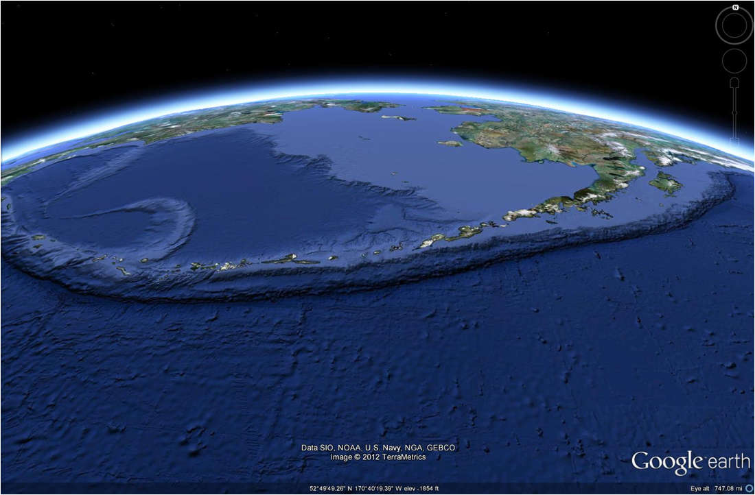
| Figure 1: The center of the Aleutian Megathrust:
a major subduction zone of massive scale. |
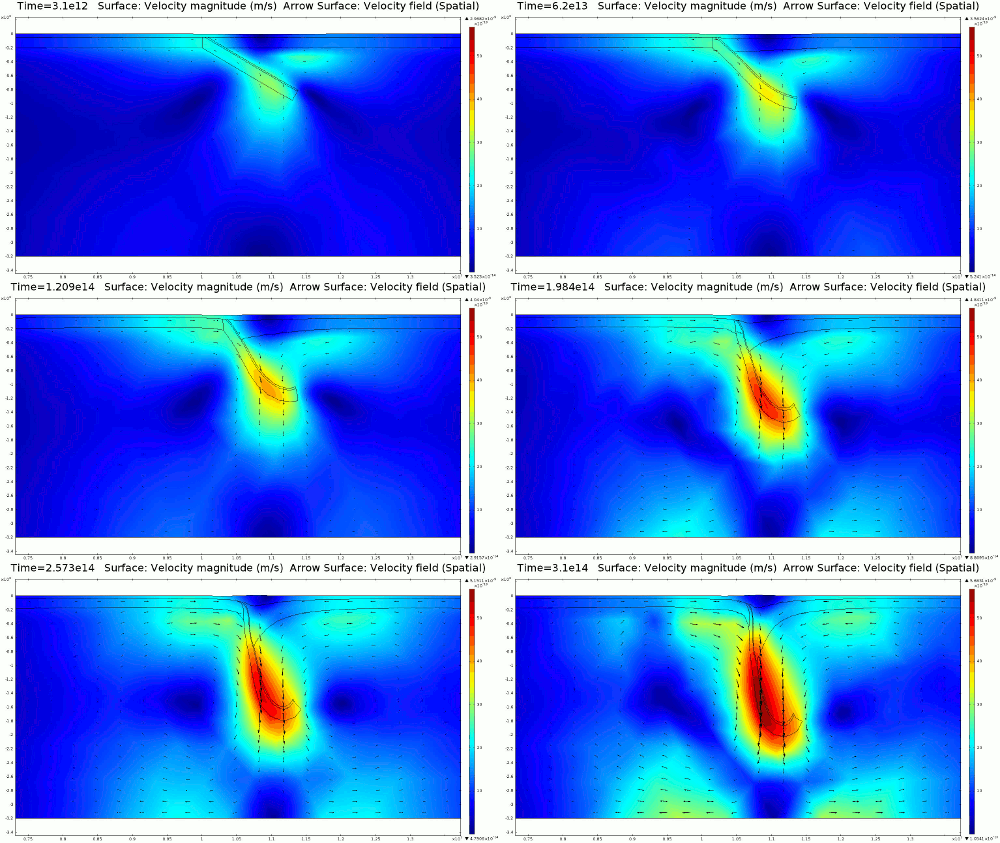
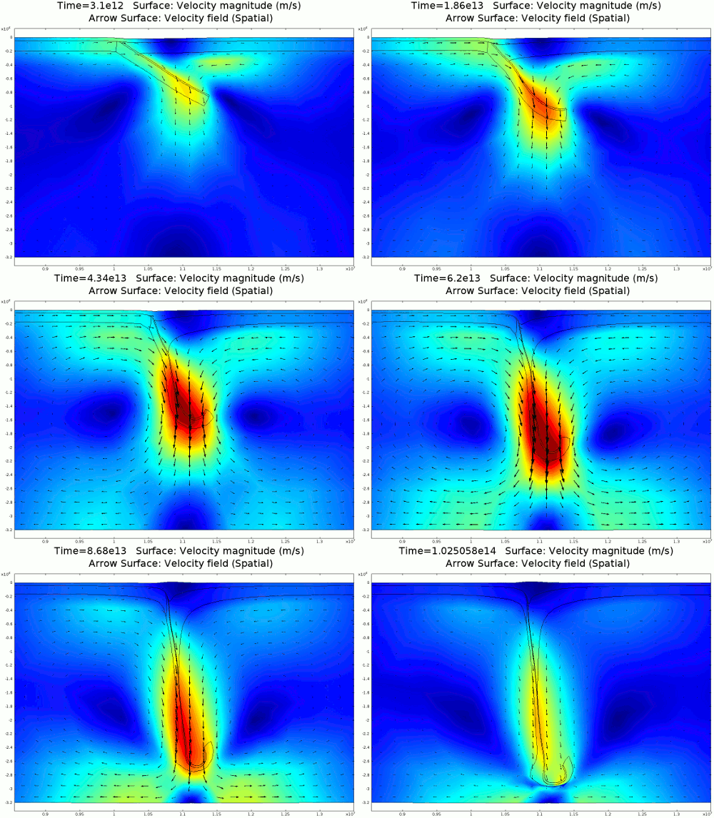
Animation 1: 2D numerical model of slab subduction.
Velocity magnitude, 1022 Pa s lithosphere. Arrows denote flow orientation. |
|---|
Two main hypotheses to explore:
1. Mantle advection controls surface deformation through mechanical coupling of lithosphere and asthenosphere.
2. The lithosphere is non-Newtonian and exhibits strain weakening behavior, this can lead to strain localization and slab detachment. Strain rate is normally greatest in the subduction hinge therefore weakening and detachment would probably occur there.
1. Introduction: The surface of the Earth takes many varying shapes, from high craggy peaks and steep gorges to rolling hills and flat coastal plains. But how and why does the Earth's surface takes its form? There are many processes that play an active role in the creation of topography and landforms, but in this module we will explore the role of mantle advection as the primary mechanism behind surface deformation (Figure 1). First, I will discuss our physical understanding of mantle dynamics, then we will use a physical model to explore the sensitivity of surface shape to various rheological conditions in the lithosphere and underlying mantle.
2. Physics A thorough understanding of surface deformation requires a thorough study of the coupling between lithosphere and the underlying mantle. We will apply the Navier-Stokes equation to define fluid movement in the Earth. For our purposes, let’s approximate the rheological properties of the lithosphere and mantle as high viscosity, incompressible fluids with no elasticity. This means that we assume the elastic and plastic properties of the lithosphere are insignificant and volumetrically dominated by the viscous behavior below, at least for the large spatial scales and long timescales we are interested in. I will now go into more detail on the derivation of Navier-Stokes, the basic equation used to define fluid flow.
2.1. Navier-Stokes derivation How is the Earth like a fluid? Fluids are able to flow, or internally deform, when a force is applied on them. Below its frictional exterior, the Earth can readily be defined as a high viscosity fluid. This force can take the form of a loading stress, where the fluid experiences pressure due to the loading of more fluid above it
(1) P = ρ g h sin(α)
where ρ is density of the fluid, g is acceleration due to gravity, h is the height of the overlying fluid, and α is the angle of the fluid surface. If the fluid boundary is not horizontal, a pressure gradient exists until the fluid deforms to once again create a horizontal surface. This deformation is opposed by the dynamic viscosity of the fluid, defined mathematically as
(2) μ = σ / εij , εij = ∂vi / ∂ j
where μ is viscosity, σ is the stress initiated by gravitational acceleration, and εij is shear strain rate, or the change in i velocity in direction j. This equation holds true for Newtonian materials, which maintain a constant viscosity regardless of a change in strain rate. If we consider equation 1 as a component driving fluid flow, and equation 2 as a component resisting fluid flow, the two will equal each other if the fluid is in a kinematic steady state:
(3) ρ g h sin(α) = μ εij
We then take the partial derivative with respect to distance of both sides to establish that this relationship is true for a gradient ∇ in all considered dimensions
(4) ∇P = μ ∇ε , ∇ = ∂ / ∂i + ∂ / ∂j + ∂ / ∂k
Notice that I do not take the partial derivative of viscosity because it is considered to be a constant here. Now we can consider a volume force established by the presence of more than one fluid with different viscosities. A fluid that is more dense than a surrounding fluid wants to sink, and it will accelerate downward until there is great enough viscosity resistance to maintain a constant, terminal velocity. The complete Navier-Stokes formula is thus
(5) ∆ρ ∂v / ∂t = ∆ ρ g - ∇P + μ ∇ε
where ∆ρg is a volume force dependent on the density difference between two fluids, and ∆ρ ∂v / ∂t is the potential acceleration of the fluid body if resisting and driving forces do not equilibrate. This equation is simple, yet it defines the behavior of all non-turbulent fluid flow. In this present form we can use Navier-Stokes to consider the problem of fluid flow as gradients across a finite element continuum in two or three dimensions, discussed further below.
2.2. Temperature dependencies for density and viscosity The mantle and lithosphere are almost continuously coupled over Earth's entirety, therefore any differential movement in the mantle can produce deformation at the surface. Both mantle and crust can be considered as highly viscous fluids, and both fluid and density are temperature dependent. This is validated by the fact that brittle rock behavior normally occurs only within the first 15 km of crust, at which depth temperatures are conducive to dislocation creep of quartz, the most abundant upper crustal mineral. The Earth's density gradient between lithosphere and asthenosphere is established by the thermal gradient produced by radioactive decay of Uranium, Thorium, their daughter products, and mantle advection. Density is linked to temperature by the phenomenological volumetric expansion of heated material
(6) ρ = ρo - αv ∆T
where ∆T is the amount of temperature change (T2-T1) experienced by the material, ρo is the original density before the change in temperature, and αv is the material specific volumetric coefficient of thermal expansion. Unlike the decrease in density with decreasing temperature caused by the phase change in water, leading to buoyant ice floating atop liquid water, rock only becomes more dense as it cools. As a result there is a density instability initiated within the upper mantle. This density instability provides a negative buoyancy force that can drive advection between the lithosphere and the rest of the mantle. A temperature rise also increases the agitation of molecular bonds in a material, and for a fluid, this causes a reduction in viscosity. Molecular agitation is opposed by confining pressures, but there is a range within the upper mantle where the effect of temperature on viscosity exceeds the confining pressure, and viscosity is greatly reduced at this depth. This weak zone of the mantle, known as the asthenosphere, holds the low viscosity condition that can allow the negative buoyancy force of the lithosphere to initiate downward advection of materials. Strain can reduce the viscosity of the material where advection is greatest for a non-Newtonian fluid, therefore a nonlinear relationship exists between the stress produced by the buoyancy force and the strain rate produced by it. Localized weakening of the lithosphere can lead to breakoff of the slab in particularly strained locations.
2.3 Non-Newtonian fluids I previously defined Newtonian fluids as those that maintain a constant viscosity regardless of the strain rate acting upon them. Non-Newtonian fluids do not hold to this constraint and viscosity will change with any change in strain rate according to the equation
(7) σn = μ ∇ε
where n is the stress exponent value that emplaces a nonlinear, power law dependency on viscosity. Most Earth materials are strain weakening, meaning that viscosity decreases with higher shear strain rate when n> 1. Some materials, such as partially crystallized magmas, fluidized corn starch, or any fluid containing suspended solids, are strain hardening, and viscosity increases with increasing shear strain rate, represented by n<1. My subduction model explores deformation patterns for Newtonian and strain weakening lithosphere.
3. Methods
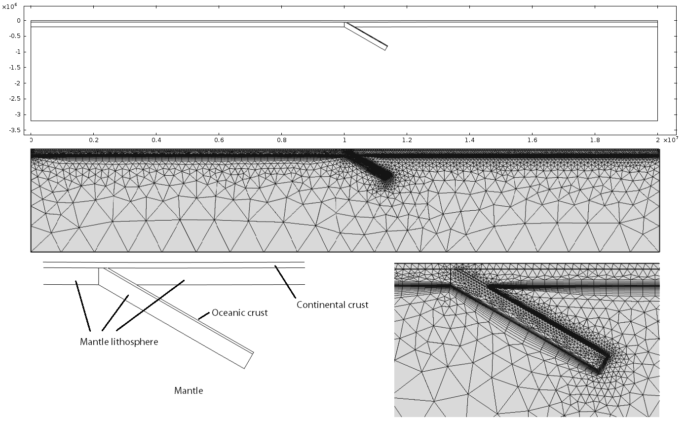
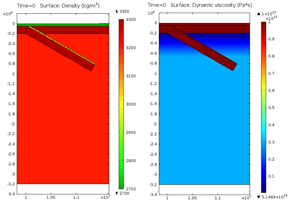
I use a numerical model to explore the link between surface deformation and mantle advection for a dominantly 2D subduction zone (Figure 2), such as the Aleutian Megathrust of Alaska. The model is a finite element, 2D, transient treatment of the Navier-Stokes equation. Fluid flow is supplemented by an alternating Lagrangian-Eularian reference frame (ALE) that allows physical deformation of the domain mesh based on velocity inputs from the Navier-Stokes solution. Materials are incompressible and momentum and mass are conserved. The mesh is triangular and is able to reconfigure its shape and resolution once an element quality threshold is met (Figure 3). Element quality is a measurement of how stretched the triangle has become due to strain; elements that diverge from an equilateral geometry will have a low element quality. The geometric extent of the domains is meant to replicate two large converging plates overlying a column of mantle that extends to the outer core.
Density and viscosity values are chosen based on composition and initial temperature. however I do not incorporate dynamic temperature (Figure 4). A density difference of 50 kg m-3 exists between the mantle lithosphere and the underlying mantle, and the volumetric contribution from oceanic and continental crust slightly reduces this difference. The first model simulations assume that all materials are Newtonian, therefore dynamic viscosity is constant regardless of strain rate. Later models incorporate strain weakening in the lithosphere, and all models have a viscosity gradient in the upper mantle.
The walls and base of the mantle are closed to all normal velocity and deformation but allow lateral movement, and the top layer imposes a normal boundary stress equal to atmospheric pressure, to replicate the surface of the Earth (Figure 5). The left boundary of the lithosphere has a normal velocity of 10 mm a-1 to replicate a far field plate velocity.
4. Results and Discussion
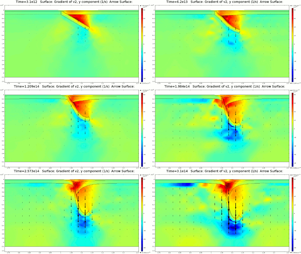
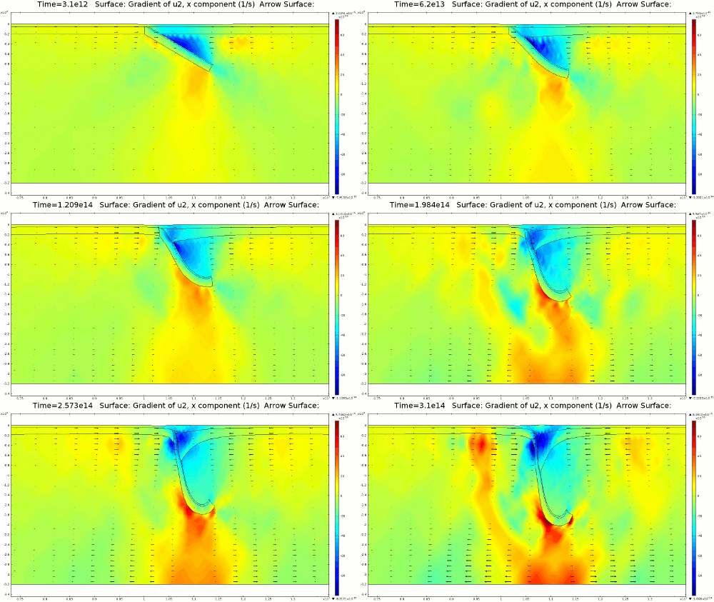
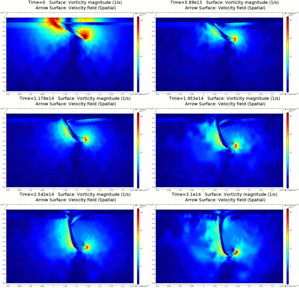
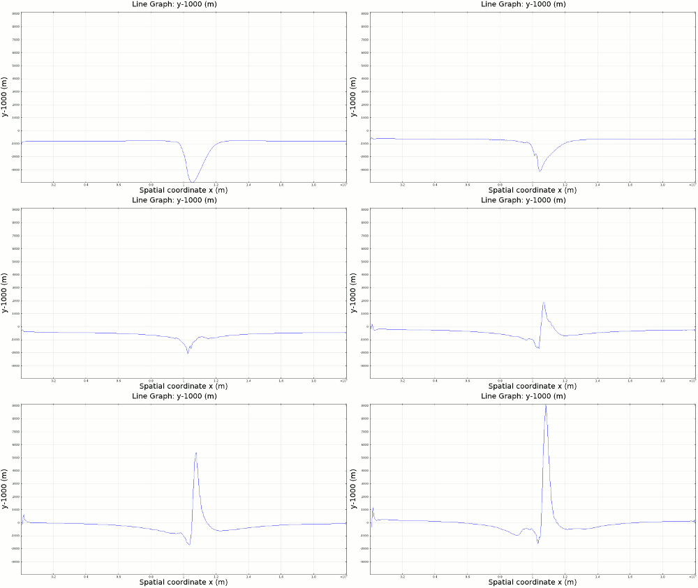
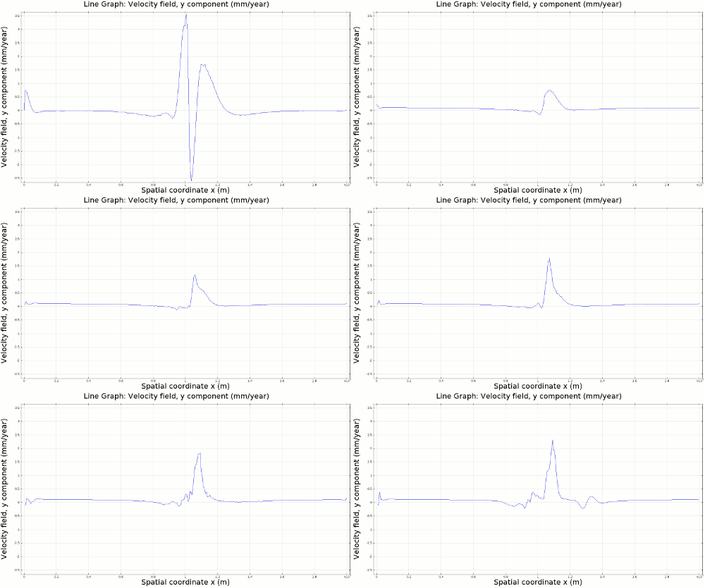
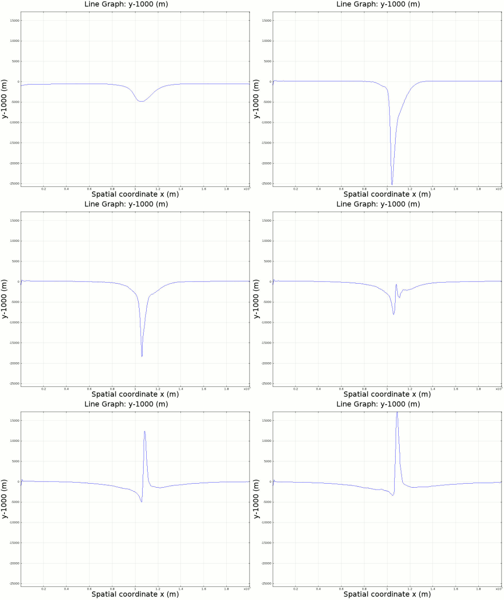
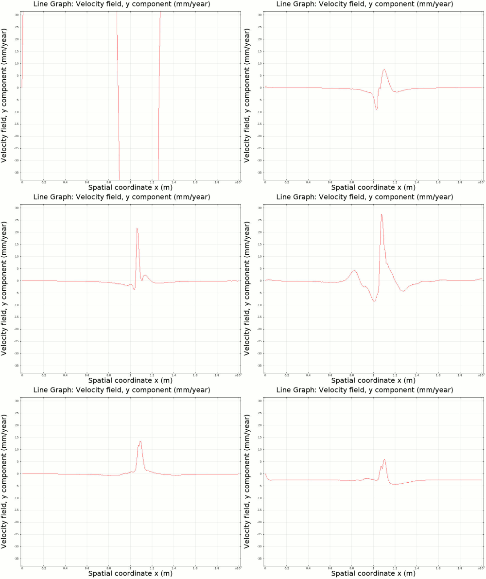
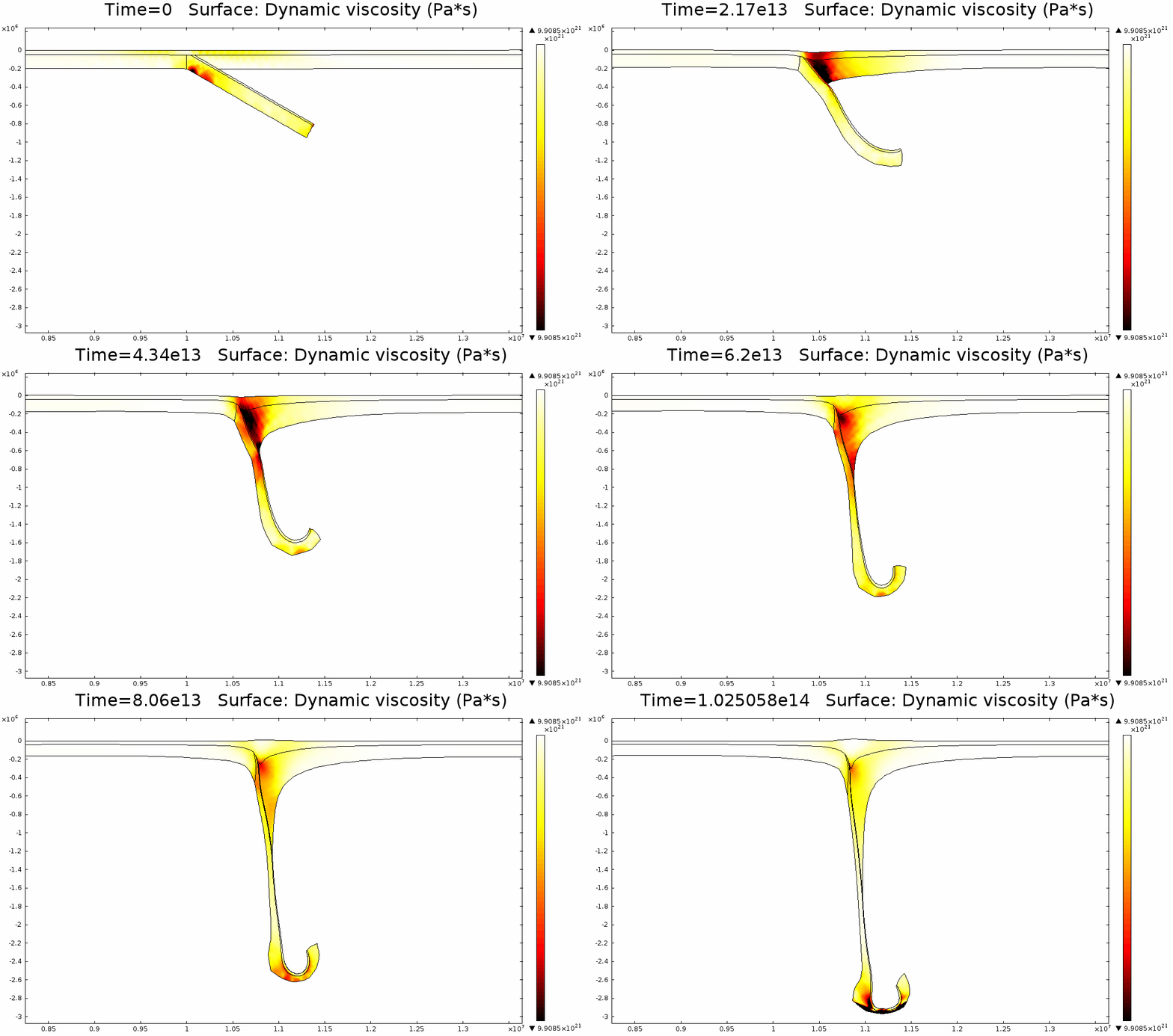
4.1. Newtonian Lithosphere Animations 1-4 display modeled velocity magnitude, normal y axis strain rates, normal x axis strain rates, and vorticity magnitude results for a Newtonian lithosphere undergoing deformation along a subducting trench for approximately 10 Ma. The negative buoyancy of the lithosphere is enough to overcome the resistance of viscosity and subduction commences. The hinge zone, or the zone where the lithosphere angles downward, rotates to accommodate a steepening angle as the slab sinks quickest from its center of mass. The mantle reacts to the sinking slab and convection cells are established along either side of the sinking slab. Mantle convection introduces a lateral velocity that, given traction to a coupled lithosphere, causes convergence just above the subducting slab, best seen in Animation 3. This zone above the subducting slab is also extended vertically, best seen in Animation 2, and the contribution of horizontal shortening and vertical extension allows a fraction of upward deformation at the surface boundary, creating topography (Animation 5-6). Deformation is dominated by the subducting slab, and any contribution from the far field plate velocity is of a lower magnitude. I reduced the viscosity slightly for a second simulation (Animation 7-9) to display the importance of this resisting component. The lithosphere quickly subducts and deforms into a "fish hook" geometry over a much shorter time scale, but also the surface topography is greatly perturbed by rapid uplift rates. A non-Newtonian model should exemplify rapid deformation for low viscosity, weakened areas, while maintaining high viscosity regions that experience little shear strain.
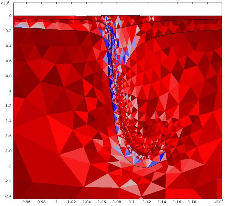
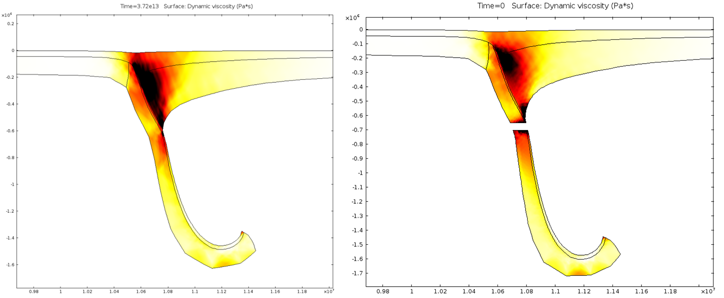
4.2. Non-Newtonian Lithosphere Figure 6 and Animation 10 display characteristic behavior of a weakly non-Newtonian lithosphere. The simulation shows the locations where we would expect shear strain weakening, namely along a dip where one would expect a reverse fault to exist. I do not incorporate an internal slip wall on this domain boundary because the geometry is too complex to approach convergence for any useful timestep, but you can see in Animation 10 that the shear strain localization fades away over time because the strain weakening isn't enough to allow effective localization to maintain an active fault zone. As the subducting slab begins to neck, strain weakening exists in the thinnest part. This could be the location where slab decoupling occurs. In the next results section I manually alter the model geometry to initiate the decoupling of the slab at this location to determine what effects would arise at the Earth's surface.
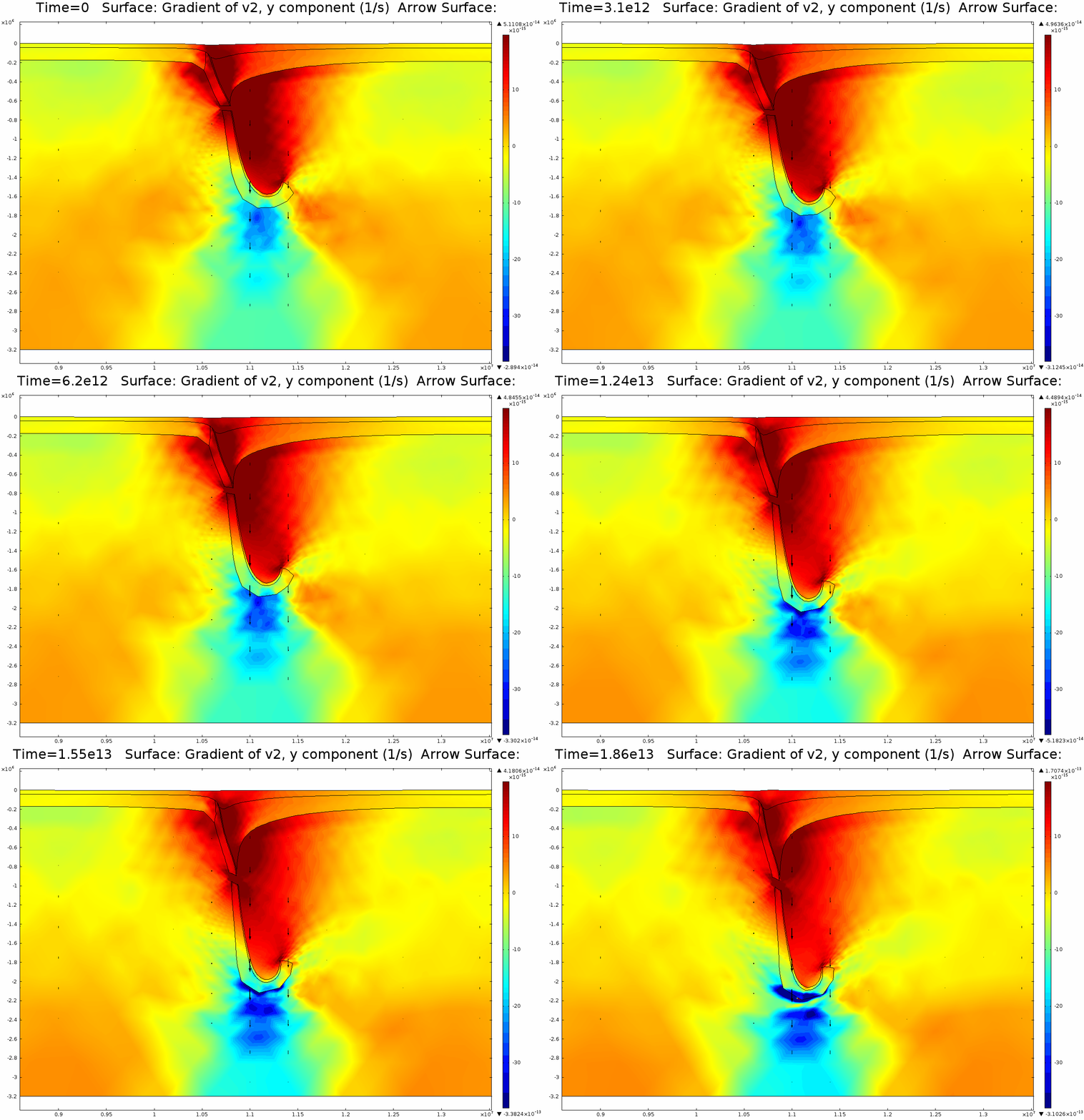
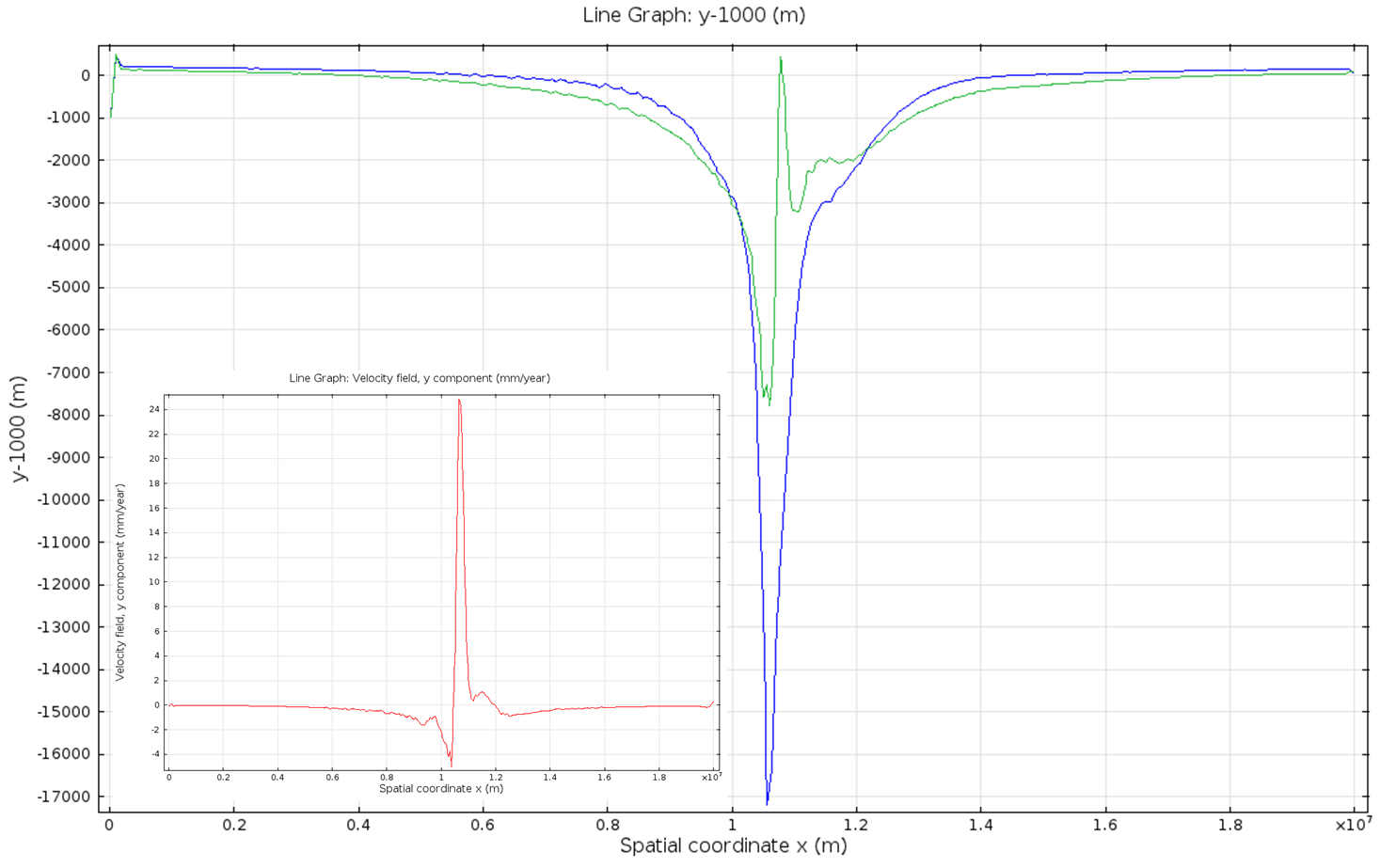
4.3. Slab Decoupling and Surface Uplift Figure 6 displays the condition of viscosity before and after the slab is decoupled. Animation 11 displays the normal vertical strain rate. The overlying lithosphere is still influenced by the foundering slab, but the gap that separates the two widens with each time step. This means that downward extension of the overlying lithosphere is reduced, and it is apparent from Figure 7 that a large proportion of this vertical extension is directed upward, to the surface. In reality, the rapid uplift would trigger nonlinear feedbacks with surface erosion, and a great deal of lithospheric exhumation would occur, exposing deeper parts of the lithosphere at the surface, possibly including ultra-high pressure metamorphic assemblages to surface. Existence of these high pressure assemblages would require a rapid mechanism of uplift such as from this decoupling slab model.
5. Summary and Conclusions The model presented here depicts a simple 2D subduction zone analogous to the Aleutian Megathrust in Alaska. the model simulates the deformation of the subducting lithosphere, the mantle, and the surface of the Earth, and deformation is predominantly driven by the negative buoyancy of the overlying lithospheric mantle, just above the Asthenosphere. Subduction is successful because the negative buoyancy of the lithosphere successfully opposes the resistant viscosity of the mantle and the lithosphere. Viscosity is the only component that resists flow in this model, and any small fluctuation (on the order of 1020 Pa s) can lead to large changes in strain rate. This model is greatly limited by an independence from a dynamic thermal gradient. Density and viscosity are based on the initial thermal gradient before subduction is initiated, but this pattern is quickly perturbed with consequences for material properties. This limitation is especially critical because model simulations typically run up to 10 Ma, which should be more than enough time to heat up a 150-200 km thick slab of lithosphere. Although many subduction zones can be largely defined in 2D, there can always be some influence in 3D that cannot be replicated by this model. This is especially true for subduction zones close to plate corners, bends in the subduction zone, lateral changes in lithosphere strength, or the existence of other foundering slabs that can incur 3D influences on an otherwise 2D system. There is no frictional behavior in this model, and no faults are established. This limitation is more important for crustal deformation, which is volumetrically only a very small component of the model, but I am concerned with surface deformation and in reality, the surface would be a frictional material, not a fluid. The model requires a higher magnitude constraint on non-Newtonian behavior to make it a truly high viscosity shear strain weakening material. Currently I can only pinpoint locations where weakening and localization would occur and initiate only small changes in dynamic viscosity, and I used this information to determine the location of slab decoupling as it is impossible for the model to decouple the slab itself. Finally, no surface mass transfer processes are employed in this model, but I would expect that higher uplift would cause a nonlinear feedback for higher erosion rates.
In conclusion, Subduction zones are thermo-gravitational systems that rely upon a thermal gradient to establish density and viscosity gradients to drive deformation. My fluid model simplifies the lithosphere and mantle and successfully replicates deformation within a subduction zone, and it can be used to determine the mechanics required in the mantle to cause uplift at the earth's surface. Substantial uplift will occur for a convergent zone with continental crust. Reduced strength in the lithosphere will amplify the rate of uplift, and decoupling of the foundering slab will also increase uplift rates potentially spanning millions of years.
.